
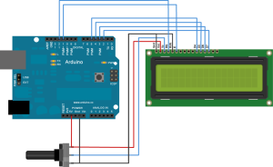
A LiquidCrystal LCD (Liquid Crystal Display) can be used in two ways:
- The normal way, with a lot of outputs (6) and wires (10).
- The I2C-way, with only 2 data-lines (SDA and SCL) and 2 powerlines (+5V, GND).
- The normal way, with a lot of outputs (6) and wires (10).
Here you can find some good explanation:
http://arduinoliquidcrystal.readthedocs.org/en/latest/liquidcrystal.html

The library for this is “LiquidCrystal.h” and that library is part of the Arduino-ide.
All functions are explained on the website above.// include the library code: #include <LiquidCrystal.h> // initialize the library with the numbers of the interface pins // LCD-ports RS E D4 D5 D6 D7 LiquidCrystal lcd(12, 11, 5, 4, 3, 2); void setup() { // set up the LCD's number of columns and rows: lcd.begin(16, 2); // Print a message to the LCD. lcd.print("hello, world!"); } void loop() { // Turn off the blinking cursor: lcd.noBlink(); delay(3000); // Turn on the blinking cursor: lcd.blink(); delay(3000); } - The I2C-way, with only 2 data-lines (SDA, the data-line and SCL, the clock-line) and 2 powerlines (+5V, GND).
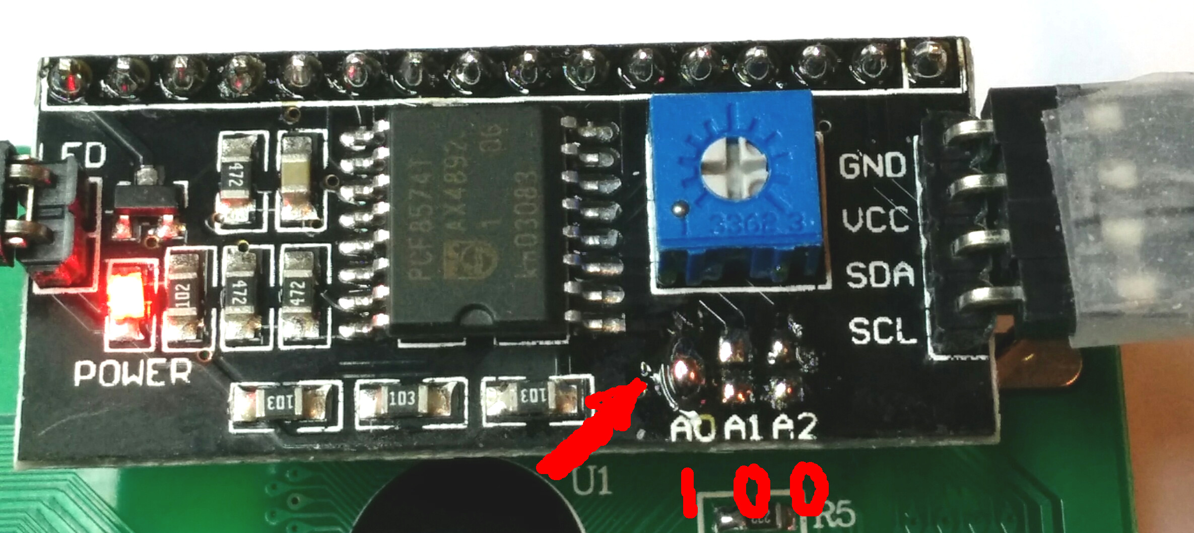
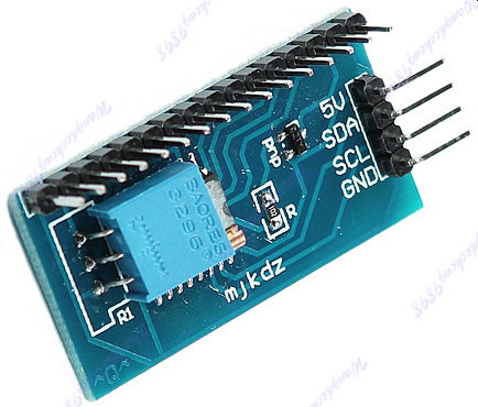
For this we need to use a ‘IO expander’ like this:
You can connect multiple devices on the I2C-bus, each device gets an address:
– 0x20 = 0010 0000,
– 0x21 = 0010 0001,
– 0x22 = 0010 0010,
– …
You can address 128 devices (= 7bit addressing), from 0 to 127).
This site explains the inner working of the I2C-protocol:
http://www.robot-electronics.co.uk/acatalog/I2C_Tutorial.html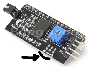 Manufacturers gives these addresses to there I2C-devices.
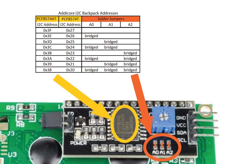
If the chip on your board is a PCF8574T, then the I2C-addresses can lay in the range of 0x20 to 0x27.
If the chip on your board is a PCF8574AT, then the I2C-addresses can lay in the range of 0x3F to 0x38.
This IO-module has a default I2C-address of 0x27, but you can change it yourself by changing the jumpers A0, A1 and A2 on the board (MARK the reverse order of A0A1A2 => A0A1A2).
E.g. For PCF8574T: A2-A1-A0 or 001 or 0x26A2A1A0 (PCF8574T) 000 = 0x27 011 = 0x24 110 = 0x21 001 = 0x26 100 = 0x23 111 = 0x20 010 = 0x25 101 = 0x22
E.g. For PCF8574AT: A2-A1-A0 or 001 or 0x3E
A2A1A0 (PCF8574AT)
000 = 0x3F    011 = 0x3C   110 = 0x39
001 = 0x3E    100 = 0x3B   111 = 0x38
010 = 0x3D    101 = 0x3A


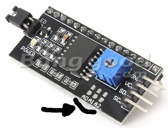

In this picture you see that ‘jumper A0’ is soldered.
So the I2C-address for this module is 0x26 or 0x3E.

(source: https://forum.micropython.org/viewtopic.php?f=14&p=19249)
- The library , called “LiquidCrystal_I2C.h“, needed for these modules to work, can be found here:
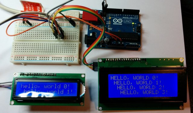
https://github.com/marcoschwartz/LiquidCrystal_I2CAlways check first if libraries aren’t available in the arduino-ide, before you download them.(Mark! Github always add ‘-master’ when you download a zip-file, unzip, rename the directory without ‘-master’, zip again and import the zip in arduino-ide) - In the following example-code, there are 2 I2C-modules used with 2 different LCD-displays (16×2 and 20×4 display), also found partly in the LiquidCrystal_V1.2.1.zip.

You also need the ‘Wire’-library.
It can be used with the same functions as in “LiquidCrystal”, only initialisation of the LCD-object is different.
LiquidCrystal_I2C lcd1(0x20,16,2); // set the LCD address of the first lcd to 0x20
                                   // for a 16 chars and 2 line display
#include <Wire.h>
#include <LiquidCrystal_I2C.h>
// library for the 'mjkds'-module
// http://hmario.home.xs4all.nl/arduino/LiquidCrystal_I2C/
LiquidCrystal_I2C lcd(0x20,16,4); // set the LCD address of the first lcd to 0x20
// for a 16 chars and 4 line display
void setup()
{
lcd.init(); // initialize the first lcd
// Print a message on the first LCD.
lcd.backlight();
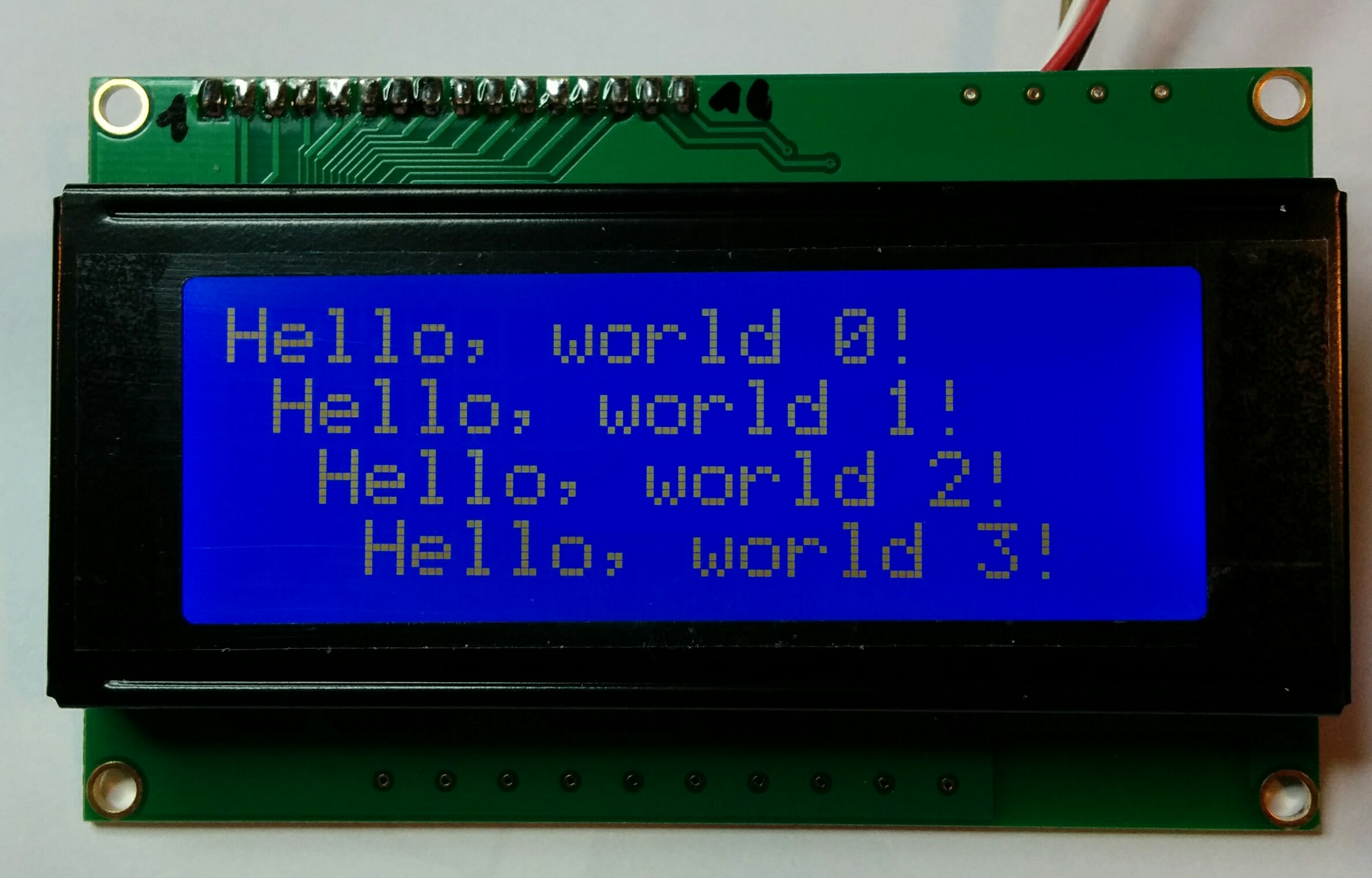
lcd.print("Hello, world 0!");
lcd.setCursor(1, 1);
lcd.print("Hello, world 1!");
lcd.setCursor(2, 2);
lcd.print("Hello, world 2!");
lcd.setCursor(3, 3);
lcd.print("Hello, world 3!");
} // end setup
void loop()
{
} // end loop
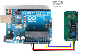
Connecting your I2C-module to an Arduino via SDA and SCL
Found here (http://tronixstuff.com/2014/12/01/tutorial-using-ds1307-and-ds3231-real-time-clock-modules-with-arduino/)
Both modules use the I2C bus, which makes connection very easy.
Moving on – first you will need to identify which pins on your Arduino or compatible boards are used for the I2C bus – these will be knows as SDA (or data) and SCL (or clock).
On Arduino Uno or compatible boards, these pins are A4 and A5 for data and clock:

 If you’re using an Arduino Mega the pins are D20 and D21 for data and clock:
 If you’re using an Pro Mini-compatible the pins are A4 and A5 for data and clock, which are parallel to the main pins, as shown below:

Other I2C-modules are available, like the ‘mjkds’-module:
The library to use for this ‘mjkdz’-module is “LiquidCrystal_I2C.h” and can be found here:
http://hmario.home.xs4all.nl/arduino/LiquidCrystal_I2C/
Mark the same name for the library, but initialisation is a bit different.
The following code is not compatible with the above chips PCF8574AT and PCF8574T!
#include <Wire.h>
// Use this library with I2C-module found on the webpage
// http://4tronix.co.uk/arduino/I2C_LCD_Module.php
#include <LiquidCrystal_I2C.h>


// set the LCD address to 0x27 for a 20 chars 4 line display
// Set the pins on the I2C chip used for LCD connections:
// addr, en,rw,rs,d4,d5,d6,d7,bl,blpol
LiquidCrystal_I2C lcd1(0x27, 2, 1, 0, 4, 5, 6, 7, 3, POSITIVE); // Set the LCD I2C address
LiquidCrystal_I2C lcd2(0x26, 2, 1, 0, 4, 5, 6, 7, 3, POSITIVE); // Set the LCD I2C address

void setup()
{
 lcd1.begin(16,2); // initialize the lcd
 lcd2.begin(20,4); // initialize the lcd
 // Print a message to the LCD.
 lcd1.backlight();
 lcd1.print("hello, world 0!");
 lcd1.setCursor(1, 1);
 lcd1.print("hello, world 1!");
// lcd1.setCursor(2, 2);
// lcd1.print("Hello, world 2!");
// lcd1.setCursor(3, 3);
// lcd1.print("Hello, world 3!");


 lcd2.backlight();
 lcd2.print("HELLO, WORLD 0!");
 lcd2.setCursor(1, 1);
 lcd2.print("HELLO, WORLD 1!");
 lcd2.setCursor(2, 2);
 lcd2.print("HELLO, WORLD 2!");
 lcd2.setCursor(3, 3);
 lcd2.print("HELLO, WORLD 3!");
}

void loop()
{
}

Hi,
Thanks for a great blog entry. It’s very helpful. One odd thing: I have an PCF8574AT chip with no jumpers soldered and a scan of the I2C bus finds it at 0x27. Anyway, it works, but the address doesn’t correspond to you table.
Scott
Hi, your article saved my day. Thank you very much.
“This very simple sketch scans the I2C-bus for devices. If a device is found, it is reported to the Arduino serial monitor.”: https://playground.arduino.cc/Main/I2cScanner/